Search Results:
Network sockets insight
posted on 14 Mar 2026 under category network
Post Meta-Data
| Date | Language | Author | Description |
|---|---|---|---|
| 14.03.2026 | English | Claus Prüfer (Chief Prüfer) | Beyond the Socket API: Understanding TCP, UDP, and Real-World Network Stack Behavior |
Beyond the Socket API: Understanding TCP, UDP, and Real-World Network Stack Behavior

Introduction
Network sockets are the basic building block that lets user space applications talk to an operating system’s networking stack. They’re everywhere—but they’re also easy to misread, and the socket API doesn’t do much to prevent common misconceptions.
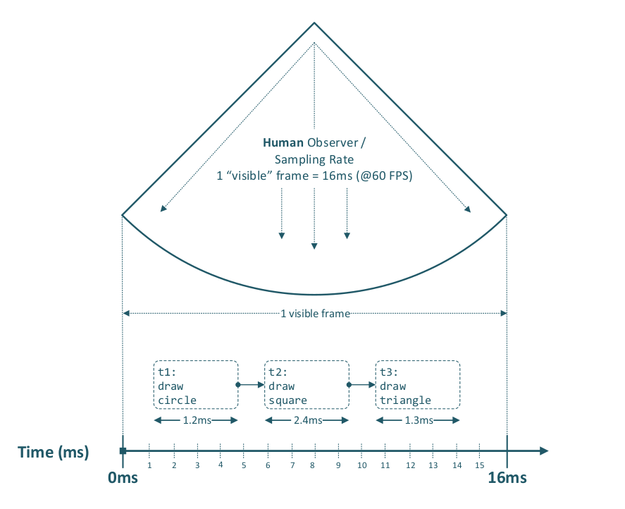
First, a brief excursion into the meaning of time and what we actually mean by “parallelism.” Back in the days of single-core processors (yes, that really was the norm), preemptive multitasking already existed. Whether something feels parallel often depends on the observer: if a computer processes three graphical tasks sequentially within 16 milliseconds (i.e., within a single frame at 60 FPS), it can look and feel parallel—even though everything actually ran in series.
The same idea applies to network sockets. Your program can send and receive packets in a given time window in serial order—and if the per-step processing time is small enough, the overall behavior is perceived as “parallel”, even when the work is actually interleaved rather than truly concurrent.
This is where many networking misunderstandings come from. Developers often overengineer solutions—spawning extra threads, opening unnecessary sockets, or choosing the wrong transport protocol—because they assume they need “more parallelism” or “more performance” than they actually do. A very typical example is thinking: “I need a second socket to send data in parallel.”
In this article, we’ll walk through the whole stack in a practical, clear way: from the historical roots of the BSD socket interface, to the kernel / user space boundary, what the OSI layers are responsible for (and what they aren’t), how TCP and UDP really behave, how congestion control changes performance expectations, why SSL/TLS integration adds real complexity. The goal is to give implementers a solid mental model—so architectural decisions are based on how the stack actually works, not on assumptions the socket API quietly leaves unchallenged.
Note that a fly has a much higher visual sampling rate—about 250 frames per second (Hz)—than a human, and therefore perceives the same motion in more discrete steps.
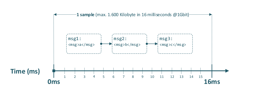
This is also applicable to Ethernet data transmission within a given time period, as the following diagram illustrates.
To illustrate that this concept has worked for decades over TCP, consider VPN tunneling: multiple client connections are multiplexed into a single VPN tunnel connection and demultiplexed at the tunnel endpoint. Over that one tunnel, two or more clients can simultaneously access a database server on port 5432 without interfering with one another.
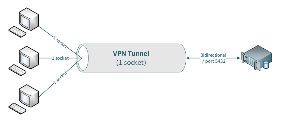
Note that even database queries with very large result sets are transmitted concurrently; packets are delivered by the TCP/IP stack (using the 5‑tuple: source IP, destination IP, source port, destination port, protocol), and are weighted-distributed across the inner sockets, while the actual packet transmission over a given link still happens in serial order within the available time window.
Historical Context
The network socket API was designed at the University of California, Berkeley as part of the 4.2BSD release in 1983, providing a portable interface to the DARPA Internet Protocols (TCP/IP). The underlying kernel network stack, including the TCP/IP implementation, has its roots in the late 1970s and early 1980s and has remained architecturally stable ever since. The guiding principle—”never change a running system”—has governed the evolution of the socket layer: the POSIX socket API that a C programmer writes against today is, in its essential structure, identical to the API that existed four decades ago1.
Linux in particular has built a reputation for a rock-solid IP stack implementation spanning Layer 2 (MAC address handling and ARP2), Layer 3 (IP routing, fragmentation, and reassembly), Layer 4 (TCP state machine), and integrated packet filtering via Netfilter / iptables / nftables / arptables. This stability is a genuine engineering achievement, but it also carries a structural limitation that has grown increasingly relevant: the IP port number space is a 16-bit unsigned integer field (RFC 793), constraining the maximum number of simultaneously addressable endpoints on a single IP address to 65,535, with the privileged range below 1024 further restricted to elevated processes. On contemporary 64-bit, multi-core hardware connected via 400 Gbit/s or 800 Gbit/s interfaces, a single physical machine is capable of sustaining connection counts and throughput rates that fundamentally exceed what the original 16-bit port field was designed to accommodate.
A further consideration of practical importance is connection idle time: empirical measurements of TCP session activity consistently show that the average connection spends more than 50% of its lifetime in an idle state, neither sending nor receiving data. In the context of kernel multi-queue NICs operating at terabit-class speeds, the combination of port space exhaustion and idle-connection overhead represents a genuine architectural tension that future network stack revisions will need to address.
Socket Subtypes
The Linux kernel socket API exposes several socket types, each with distinct semantics, protocol bindings, and applicable use cases. The following subtypes are of primary relevance to Ethernet-based networking.
SOCK_STREAM — TCP (RFC 7933, RFC 92934)
SOCK_STREAM with IPPROTO_TCP implements the Transmission Control Protocol, providing a reliable, ordered, error-checked, full-duplex byte stream between two endpoints. TCP performs connection establishment via the three-way handshake, flow control via sliding window, congestion control via multiple standardised algorithms (Reno, CUBIC, Vegas, BBR), and retransmission of lost segments. It is the appropriate transport for applications requiring delivery guarantees: HTTP, FTP, SMTP, IMAP, SMB, SSH and the overwhelming majority of application-layer protocols.
SOCK_DGRAM — UDP (RFC 7685)
SOCK_DGRAM with IPPROTO_UDP implements the User Datagram Protocol, offering a connectionless, unreliable, message-oriented datagram service. UDP provides no delivery guarantee, no ordering guarantee, and no retransmission mechanism; each datagram is dispatched independently and may be lost, duplicated, or reordered in transit. UDP is the appropriate transport for latency-sensitive applications that can tolerate packet loss and require minimal protocol overhead.
SOCK_DGRAM — UDP-Lite (RFC 38286)
SOCK_DGRAM with IPPROTO_UDPLITE implements UDP-Lite, a variant of UDP that introduces a partial checksum coverage field, allowing the checksum to protect only a configurable header prefix while leaving the payload intentionally unchecked. This is specifically useful for real-time multimedia transmission over lossy links (e.g., wireless), where a packet with a corrupted payload is preferable to no packet at all—allowing the application-layer codec to perform its own error concealment rather than discarding the datagram entirely at the transport layer.
SOCK_SEQPACKET
SOCK_SEQPACKET provides a sequenced, reliable, connection-oriented, bidirectional transport with preserved message boundaries. Its primary practical deployment domain on Linux is the AF_UNIX (local inter-process communication) address family, where it guarantees in-order, loss-free delivery of fixed-boundary messages between processes on the same host without the overhead of a full TCP/IP stack. It is not designed or suitable for use across network segments.
Network Abstraction
Modern networking is structured according to the layered OSI reference model, standardised by the ISO as ISO/IEC 7498-17, which partitions the communication stack into discrete, encapsulated layers to enable interoperability across heterogeneous hardware and software implementations. An implementor of socket-based applications must be familiar with this model; failure to internalise the layering invariants is the origin of a disproportionate number of subtle socket programming errors encountered in production systems.
User Space and Kernel Space
Before summarizing the OSI layer model, it is also important to understand modern CPU privilege separation, because it adds another layer of complexity. If you are not aware of it, it becomes an additional and frequent source of implementation mistakes during development.
The x86-64 architecture implements hardware-enforced privilege rings. The operating system kernel executes at Ring 0, which grants unrestricted access to hardware registers, physical memory, and privileged instructions. User space applications execute at Ring 3, which is physically isolated from Ring 0: a Ring 3 process cannot read or write kernel memory directly, cannot execute privileged instructions, and cannot configure hardware interfaces without kernel mediation.
This separation has a direct and non-trivial impact on socket programming. Every socket operation that crosses the user space / kernel boundary—socket(), bind(), listen(), accept(), connect(), send(), recv(), read(), write(), close(), setsockopt()—is a system call: a controlled gate through which execution transfers from Ring 3 to Ring 0, the kernel performs the requested operation in a trusted execution context, and control returns to Ring 3 with a result code. Each such transition carries measurable overhead (context save / restore, TLB interactions, potential cache eviction) that accumulates at high I/O rates.
A critical corollary for implementors: the kernel network stack is a sovereign subsystem. User space code can configure it through setsockopt() knobs, influence its behaviour via socket buffer sizing (SO_SNDBUF, SO_RCVBUF) and option flags (TCP_NODELAY, TCP_CORK, SO_REUSEPORT), and observe its state through getsockopt() and /proc/net interfaces—but it cannot override or bypass the kernel’s packet processing logic. Observed “unexpected” socket semantics—delayed acknowledgements, coalesced writes, spurious RST generation—are invariably the kernel implementing its specified behaviour correctly; the implementor’s mental model is what requires correction.
The OSI Model and Network Layers
The OSI reference model defines seven protocol layers, but in real IP networks these layers are not an academic chart—they form a dependency chain. Socket programming only works reliably if you understand how each layer provides prerequisites for the next: Layer 2 reachability must exist before IP can deliver packets on a network segment, IP addressing and routing must be correct before TCP/UDP can carry application data, and most applications will not function at all unless naming and configuration are in place7.
In practice, the protocols that bind these layers together—ARP, DHCP, and DNS—are frequent root causes of “socket problems” that are incorrectly blamed on TCP or UDP. ARP resolves IP addresses to MAC addresses, DHCP supplies addressing, routing, and resolver configuration, and DNS maps service names to endpoints. If any of these fail (or cache stale data), the symptom in user space is often the same: timeouts, connection failures, or seemingly random behaviour.
Especially network misconfigurations can lead to misguided assumptions, which in turn produce incorrect (and sometimes dangerous) code.
For socket programming, the following layers are of direct operational relevance.
Layer 1 — Physical
The physical layer governs the electrical, optical, or radio transmission of raw bit streams over the physical medium. For Ethernet, this encompasses cable specifications (Cat5e/6/6A/8), optical fibre, connector standards, and signalling rates. The physical layer is entirely transparent to socket programming but determines the raw bandwidth ceiling and physical error rates that all higher layers must operate within.
Layer 2 — Data Link (Ethernet)
The data link layer is responsible for node-to-node data transfer on a shared medium, including MAC address resolution (ARP2), Ethernet frame encapsulation (IEEE 802.38), VLAN tagging (IEEE 802.1Q9), and flow control at the link level (IEEE 802.3x PAUSE frames10). ARP maps Layer 3 IP addresses to Layer 2 MAC addresses within a broadcast domain. The kernel manages all Layer 2 processing transparently.
Layer 3 — Network (IP)
The network layer handles end-to-end packet routing across heterogeneous networks. IPv4 (RFC 79111) and IPv6 (RFC 820012) encapsulate Layer 4 segments into packets, perform fragmentation and reassembly and carry the source and destination IP addresses that identify communicating hosts globally. The kernel IP routing table, managed via ip route or netlink, determines the outbound interface and next-hop gateway for each transmitted packet.
Layer 4 — Transport (TCP/UDP)
The transport layer provides end-to-end communication services between processes on different hosts. TCP (SOCK_STREAM, port-based demultiplexing, reliable ordered delivery, flow and congestion control) and UDP (SOCK_DGRAM, connectionless, unreliable, minimal overhead) are the two dominant Layer 4 protocols; this article addresses both in depth below. The 16-bit source and destination port numbers in the Layer 4 header, combined with the source and destination IP addresses from Layer 3, form the 4-tuple that uniquely identifies a connection within the kernel’s socket table.
Layer 7 — Application
The application layer encompasses all application-specific protocols: DNS, DHCP, NTP, HTTP, FTP, SMTP, IMAP, SMB, BGP, L2TP, PPTP and custom binary or text-based protocols. From a socket programming perspective, the application layer is the domain of user space code; the socket API provides the interface between Layer 4 and the application. All protocol design decisions—framing, serialisation, authentication, error handling—that are not delegated to lower layers must be implemented at Layer 7.
Protocol Subtypes
The socket API’s three principal Ethernet-capable subtypes—SOCK_STREAM (TCP), SOCK_DGRAM (UDP), and SOCK_DGRAM with IPPROTO_UDPLITE (UDP-Lite)—each carry a distinct set of guarantees and trade-offs. Choosing the wrong subtype for an application is one of the most consequential architectural mistakes a developer can make, and it is rarely recoverable without a redesign. The sections below examine each protocol in depth: its mapping to a socket subtype, its fundamental characteristics, and the specific mechanisms that define its behaviour under real network conditions.
TCP
SOCK_STREAM with IPPROTO_TCP maps directly to the Transmission Control Protocol (RFC 7933, updated by RFC 92934). TCP provides a reliable, ordered, full-duplex byte stream between two endpoints. Before any application data is exchanged, TCP establishes a connection through the three-way handshake:
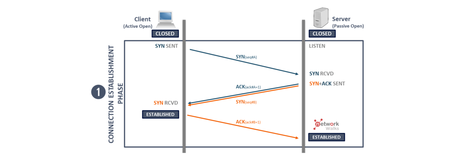
The diagram is from network Walks and the following article explains the 3 way handshake in detail: https://networkwalks.com/tcp-3-way-handshake-process/
The core characteristics of a TCP socket are:
- Reliability: every byte sent is acknowledged; lost segments are retransmitted automatically.
- Ordering: bytes arrive at the receiver in the exact order they were sent.
- Flow control: the receiver regulates the sender’s rate to protect its own buffers.
- Congestion control: the sender adapts its rate to network capacity to prevent collapse.
- Full-duplex: data flows independently in both directions on a single connection.
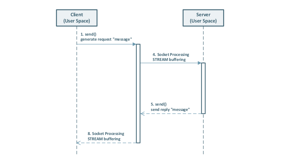
Full UML sequence diagram of a SOCK_STREAM flow: 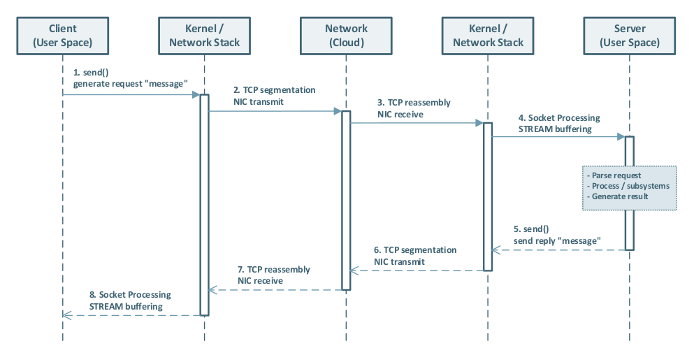
The following sub-sections detail the two most operationally significant TCP mechanisms: flow control and congestion control.
Flow Control
Flow control is the mechanism by which a TCP receiver tells the sender how much data it is currently able to accept. The fundamental problem it solves is simple: if a fast sender continuously writes data faster than the receiver’s application can consume it, the receiver’s kernel buffer will eventually fill up, and the kernel will have to drop incoming segments—wasting bandwidth and triggering retransmissions. Flow control prevents this by giving the receiver a voice in the conversation.
Congestion Control
Congestion control is the mechanism by which a TCP sender adapts its transmission rate to the capacity of the network path, not just the capacity of the receiver. The problem it solves is distinct from flow control: even if the receiver has plenty of buffer space, the intervening routers and switches along the path may not. Without congestion control, a sender that ignores network capacity will cause routers to drop packets, triggering retransmissions from all competing senders simultaneously—a phenomenon known as congestion collapse (RFC 89613). TCP congestion control prevents this by having each sender independently estimate the current available bandwidth and back off when loss or delay signals indicate that the network is overloaded.
UDP
SOCK_DGRAM with IPPROTO_UDP maps to the User Datagram Protocol (RFC 7685). UDP is the deliberate opposite of TCP: it provides a connectionless, unreliable, message-oriented datagram service with minimal protocol overhead. There is no handshake, no connection state, no delivery guarantee, no ordering guarantee, and no retransmission mechanism. Each datagram is a self-contained unit that is dispatched independently and may be lost, duplicated, or reordered in transit.
The socket subtype characteristics are:
- Connectionless:
sendto()andrecvfrom()identify the peer per-datagram; noconnect()/accept()cycle is required (thoughconnect()may be called on a UDP socket to set a default destination address). - Message boundaries preserved: unlike TCP’s byte stream, a single
sendto()call produces exactly one datagram; a matchingrecvfrom()call returns exactly that datagram or nothing. - No flow or congestion control: the sender may transmit at any rate regardless of receiver or network capacity; the application is entirely responsible for rate management.
- Minimal header overhead: the UDP header is 8 bytes (source port, destination port, length, checksum); TCP’s minimum header is 20 bytes with typical options adding further overhead.
UDP is the correct choice for latency-sensitive applications that can tolerate or conceal packet loss: real-time audio and video streaming, online gaming or for protocols that implement application‑level reliability.
UDP Lite
SOCK_DGRAM with IPPROTO_UDPLITE maps to UDP-Lite (RFC 38286), a specialised variant of UDP designed for real-time multimedia transmission over lossy links such as wireless networks. UDP-Lite introduces a single new header field—the Checksum Coverage field—that allows the checksum to protect only a configurable prefix of the datagram (covering at minimum the 8-byte header) while leaving the remainder of the payload intentionally unchecked.
The socket subtype characteristics are:
- Partial checksum coverage: the
UDPLITE_SEND_CSCOVandUDPLITE_RECV_CSCOVsocket options (viasetsockopt()) control how many bytes are included in the checksum on send and the minimum coverage required on receive, respectively. - Tolerates payload corruption: a datagram with a corrupt payload but a valid header checksum is delivered to the application rather than silently discarded at the kernel level. The application-layer codec (e.g., an audio or video decoder) can then perform error concealment on the corrupt payload—producing degraded-but-audible or degraded-but-visible output—rather than receiving no data at all.
- Same connectionless semantics as UDP: there is no connection state, no ordering, and no retransmission.
UDP-Lite is not a general-purpose replacement for UDP. It is appropriate only for applications specifically engineered to exploit partial delivery: multimedia codecs, sensor telemetry, and similar domains where a damaged sample is more useful than a missing one.
Ethernet Peripherals
The socket API and the kernel’s TCP/IP stack do not operate in isolation. Every packet that leaves a host traverses one or more physical network devices before reaching its destination. Understanding the basic operational characteristics of these devices is essential for diagnosing socket performance problems: a misconfigured switch or router is frequently the actual root cause of what appears, from the application’s perspective, to be a TCP or UDP problem. The following sub-sections describe the three categories of network device most relevant to socket programming:
- Ethernet Switches
- IP Routers
- Firewalls
Any of these devices could alter packets on their way to the destination, this also can lead to confusion. Tools like wireshark or tcpdump are inevitable!
Ethernet Switches
An Ethernet switch is a Layer 2 forwarding device. It operates on MAC addresses and Ethernet frames—below the IP layer, and entirely below the TCP/UDP layer. A switch’s primary function is to learn which MAC addresses are reachable on each of its physical ports (by inspecting the source MAC address of incoming frames) and to forward frames only to the port where the destination MAC address has been learned, rather than flooding the frame to all ports (oldfashioned HUB behaviour). This process is performed entirely in hardware on modern managed switches, at wire speed and with sub-microsecond per-port latency.
From a socket programming perspective, the switch is normally invisible: the kernel sends an Ethernet frame, the switch delivers it, and the receiving host’s kernel passes the payload up the IP stack. However, switch behaviour becomes directly observable under two conditions:
- Queue saturation: when ingress traffic exceeds the switch’s switching capacity or the egress port’s bandwidth, frames are queued. If the queue is full, frames are dropped silently (tail-drop), causing TCP retransmissions and throughput collapse.
- Flow control interaction: IEEE 802.3x PAUSE frames, described in detail later, can help prevent the Queue saturation problem, but require consistent configuration across the entire switch path to be effective.
Modern managed switches are frequently Layer-3 capable devices as well. A Layer-3 switch (also called a routing switch) can perform IP routing between VLANs entirely in hardware, without requiring a dedicated router. This is a common design in enterprise and data-centre environments where low-latency inter-VLAN9 routing and high port density are required simultaneously. Also common in enterprise designs is IEEE 802.3ad link aggregation (channel bonding)14 to increase aggregate bandwidth and provide redundancy across multiple physical links.
IP Router
An IP router is called a “Layer 3 forwarding device”. It operates on IP addresses and packets—above the Ethernet frame layer, but below TCP and UDP. A router’s primary function is to receive an IP packet on one interface, consult its routing table to determine the best next-hop for the packet’s destination address, and forward the packet out the appropriate interface, decrementing the TTL and recomputing the IP header checksum in the process.
From a socket programming perspective, a correctly operating router is also invisible: packets are forwarded transparently between router interfaces (IP subnets).
Misconfigured router devices can cause unpredicted packet behaviour and also causing network sockets to misbehave.
Firewalls
Firewalls inspect and filter network traffic at one or more protocol layers. The relevant categories from a socket-programming perspective are:
- Layer 2 (MAC-level) firewalls: operate on Ethernet frames and filter by MAC address, VLAN tag, or EtherType. They are typically implemented as transparent bridges and are invisible to IP-layer devices. Useful for isolating segments at the Ethernet layer without IP address assignment.
- Layer 3 (Network-level / packet-filter) firewalls: operate on IP packets and filter by source / destination IP address, CIDR prefix, protocol number (TCP, UDP, ICMP), and Layer 4 port number. Linux Netfilter (iptables / nftables) is the canonical implementation. These are the most common firewalls in practice.
- Layer 7 (Application-level / next-generation) firewalls: perform Deep Packet Inspection (DPI), reconstructing application-layer streams to identify protocol signatures, HTTP URLs, TLS SNI fields, and DNS query names. They can block or rate-limit traffic based on application identity rather than just addresses and ports.
From a socket-programming perspective, firewalls at any layer can silently drop packets—leading to retransmissions, elevated latency, or connection failures that are indistinguishable from network congestion. Always verify firewall rules when diagnosing unexplained socket behaviour.
TCP / Network Characteristics
The following section discusses the main characteristics of TCP. The article’s final paragraph “Advanced Topics” highlights a few advanced topics that a developer may also want to understand—depending heavily on the specific requirements and environment—when designing and implementing a new protocol.
TCP Reliability
TCP ensures reliable delivery through several key mechanisms:
- Sequence numbers and acknowledgments: Every byte sent is assigned a sequence number. The receiver acknowledges received bytes, allowing the sender to detect loss and trigger retransmissions.
- Duplicate detection: Incoming packets are matched against sequence numbers. Duplicates (whether from retransmissions or network anomalies) are automatically discarded by the receiver’s TCP stack.
- Out-of-order assembly: Although packets may traverse different network paths and arrive out of order, TCP’s sequence number mechanism reorders them before delivering data to the application.
- Checksum validation: Each TCP segment includes a checksum to detect corruption in transit. Corrupted segments are discarded, triggering automatic retransmission.
- Automatic retransmission: Lost segments trigger timeouts and retransmission without application involvement, making the process transparent to the application layer.
Together, these mechanisms provide applications with a reliable, in-order byte stream, even when the underlying network drops, duplicates, or reorders packets.
TCP Retransmissions
When a TCP segment is lost in transit, the sender must retransmit it. The key concept governing when a retransmission is triggered is the Retransmission Timeout (RTO). The RTO is a dynamically calculated timer maintained by the kernel for each TCP connection: if no acknowledgement (ACK) is received within the RTO interval after a segment was sent, the segment is considered lost and retransmitted.
The RTO value is computed from the measured Round-Trip Time (RTT) of the connection using the algorithm specified in RFC 629815. On Linux, the RTO has a lower bound of 200 milliseconds and an upper bound of 120 seconds.
Exponential backoff: Each consecutive retransmission failure causes the RTO to double—this is known as exponential backoff (also called binary exponential backoff).
The doubling continues until the connection is declared dead (after tcp_retries2 attempts, defaulting to 15 on Linux, which can take up to ~924 seconds in the worst case) or until an ACK is received. This backoff mechanism prevents retransmissions from flooding a network that is already congested.
In practice, transient packet loss (e.g., from a brief routing hiccup) is healed within one or two retransmission attempts—typically well under one second on a well-configured network. The exponential backoff ensures that worst-case scenarios do not compound network congestion.
IEEE 802.3x
IEEE 802.3x10 PAUSE frames operate at Layer 2—below the IP and TCP layers. When a switch port’s ingress queue becomes congested, it can send a PAUSE frame to the sender (NIC or upstream switch port). The sender will then temporarily stop transmitting for the specified pause time. Once the receiving side can accept traffic again, normal transmission resumes (either after the pause timer expires, or sooner if a subsequent PAUSE frame with a pause time of 0 is sent).
Despite some wild claims on the internet, in my opinion it does not generally hurt to enable IEEE 802.3x PAUSE frames—provided the feature is enabled consistently and intentionally across the network, and you understand the side effects.
There is a simple physical rule: if a pipe is full, no more water can flow through it. Networking equipment behaves similarly: if an ingress queue cannot be drained (i.e., packets cannot be processed and forwarded fast enough), then no QoS policy, socket behavior, or higher-layer mechanism can magically make additional packets fit into that already-full queue. At that point, you have a scaling and / or design problem—“Houston, we have a network misconfiguration.”
So, with or without IEEE 802.3x PAUSE frames enabled, a full queue is still a full queue. PAUSE frames don’t “increase capacity”; they mainly help absorb short traffic bursts and micro-congestion scenarios where the queue can recover quickly. In such cases, PAUSE frames can significantly reduce packet loss and, as a consequence, reduce TCP retransmissions and application-level timeouts.
A good network design—including QoS (Quality of Service) and proper monitoring—helps prevent these scenarios in the first place.
Also consider IEEE 802.1p (the VLAN priority / CoS marking mechanism). It is not a successor to IEEE 802.3x, but a complementary feature: 802.1p classifies and marks traffic into Classes of Service (Layer 2 priority), enabling switches to apply QoS policies and queue scheduling per class. However, it does not provide per-socket or per-connection, end-to-end flow control, nor does it solve congestion by itself—its effectiveness depends on consistent QoS configuration across the network.
Network Address Translation
Network Address Translation (NAT) is a mechanism by which a router rewrites the source or destination IP address (and port number) of packets as they pass through it. The primary motivation for NAT in IPv411 is address exhaustion: the IPv4 address space (approximately 4.3 billion addresses, RFC 791) was allocated before the scale of the modern internet was understood, and a typical home or office network receives only one public IPv4 address from its ISP. NAT allows many devices behind that single address to initiate outbound connections—each assigned a unique source port in the router’s translation table—while appearing to the outside world as one IP address.
IPv6 and the end of NAT: IPv6 provides a 128-bit address space—effectively unlimited for any foreseeable use case. With IPv6, every device can receive a globally unique, routable address, which eliminates the technical necessity for NAT. End-to-end connectivity is restored, simplifying protocols that were designed for a world without address translation. IPv6 adoption is therefore the long-term path away from NAT complexity.
Network Congestion / Multiplexing
One last remark before diving into socket details (and showing some sample code) is worth making: real-world “bad network” scenarios can strongly influence packet transmission behavior.
A common mistake is to assume that “parallel” processing can magically fix transmission problems. But congestion is fundamentally a capacity / queueing issue: a congested link is a congested link. Until it can drain again, packets will be delayed or dropped—no amount of application-side parallelism changes that.
A robust mitigation—especially for high-availability and ultra-low-loss requirements—is packet duplication across truly independent paths (or links), so that transient loss on one path does not necessarily impact delivery. More generally, improving resilience against congestion requires adding independent capacity (for example, redundant uplinks or diverse routing paths). These designs are uncommon in typical customer networks, but they are well-established in environments that prioritize determinism and availability.
Examples of problematic scenarios include:
- Wi‑Fi interference, e.g., radar detection / avoidance (DFS), high noise floors, hidden-node problems, and contention in crowded environments
- Internet edge / router congestion, e.g., overloaded uplinks, poor buffer management, and peering bottlenecks
Wi‑Fi 7 (and future generations) use multi-antenna and multi-link techniques that can improve stability and resilience in many environments—provided the client and infrastructure support them and the RF conditions are reasonable. However, this is not the same as packet duplication: Wi‑Fi 7/8 do not inherently duplicate each packet across independent links / antennas in the way industrial redundancy mechanisms do. If the transmission path currently in use is blocked (e.g., due to interference or medium contention), frames are delayed or lost, which can trigger TCP retransmissions (for TCP-based applications).
On a single physical link global congestion blocks any traffic.
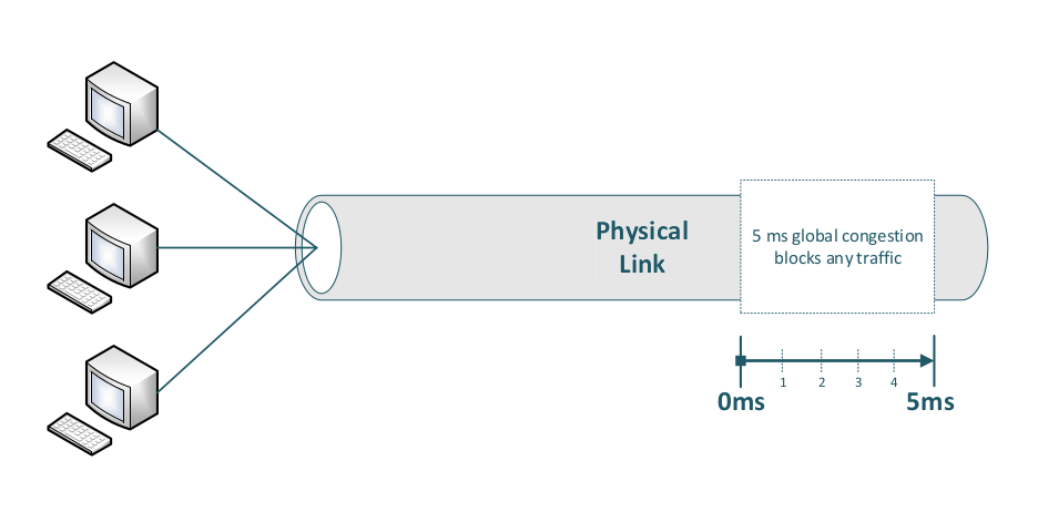
Only packet duplication across two truly independent physical links can help mitigate this problem.
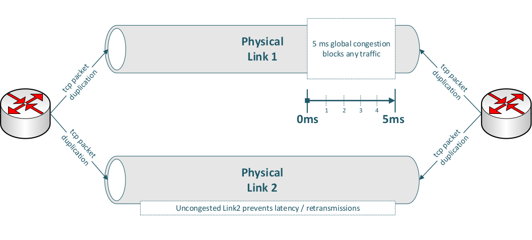
-
As a practical example, you can achieve this by configuring port mirroring (packet duplication) between two endpoints—provided the sender duplicates packets and the receiver also duplicates the corresponding response packets.
-
On a Linux router, you can also add IP filters for source and destination addresses; this is particularly well-suited to IPv6, where straightforward source–destination address rules can be applied.
Client / Server Handling
Now, if all circumstances are truly favorable (having learned from 3-way handshakes across multiple ethernet devices, packet alteration, and similar challenges), circumstances still have a high susceptibility to error caused by human or machine factors. We assume all conditions are good and that we have excellent networking engineers configuring our network. Linux is also an excellent partner in network processing, socket programming, and stability.
We have also learned that TCP RTO timeouts are low on Linux systems (starting at 200 milliseconds), so retransmissions from occasionally occurring packet re-routing or similar packet drops will be healed in < 1 second with 2 consecutive retransmissions.
The TCP stack includes all these mechanisms for us, so our demo code (application layer) does not have to cope with these nasty scenarios and we can concentrate on our networking application. Therefore, our following code will exclusively focus on SOCK_STREAM (TCP) sockets.
Server Accept (Blocking)
The following example will set up a blocking socket listening on all interfaces (IPv4 address 0.0.0.0) on port 1234, wait for the first connection (accept()) and afterward exit.
The difference and impacts between blocking and non-blocking sockets will be discussed in the following chapters.
#include <stdio.h>
#include <stdlib.h>
#include <string.h>
#include <sys/types.h>
#include <sys/socket.h>
#include <netinet/in.h>

int opt = 1;
struct sockaddr_in addr;
struct sockaddr_in client_addr;
socklen_t addrlen = sizeof(client_addr);

memset(&addr, 0, sizeof(addr));
addr.sin_family = AF_INET;
addr.sin_addr.s_addr = INADDR_ANY;

// set listening port
addr.sin_port = htons(1234);

// setup server socket
int server_fd = socket(AF_INET, SOCK_STREAM, IPPROTO_TCP);
setsockopt(server_fd, SOL_SOCKET, SO_REUSEADDR, &opt, sizeof(opt));
bind(server_fd, (struct sockaddr *)&addr, sizeof(addr)); // bind socket
listen(server_fd, SOMAXCONN); // kernel: allocate backlog queue

int client_fd = accept(server_fd, (struct sockaddr *)&client_addr, &addrlen);
// client_fd: new fd for this specific client connection
// server_fd: remains open, continues accepting new connections
// the accept() call will block (wait) until a new connection has been set up
A listening socket is the server’s entry point: it is a file descriptor created with socket(), configured with options, bound to a network address and port with bind(), and then placed into the LISTEN state with listen(). The key socket options used above are:
-
SO_REUSEADDR: allows the server to bind to an address / port combination that is still in theTIME_WAITstate from a previous run—essential for servers that need to restart quickly without waiting for the kernel to release the port. -
SOMAXCONN(passed tolisten()): tells the kernel how large the backlog queue of completed-but-not-yet-accepted connections should be. The kernel caps this at its internal maximum (typically 4096 on modern Linux).
Server Client Handling
Once in LISTEN state (server_fd), the kernel autonomously completes incoming three-way handshakes and places the resulting connections in the backlog queue. Each call to accept() dequeues one entry and returns a connected socket (client_fd)—a new, distinct file descriptor that represents the specific bidirectional byte stream to that one client. The listening socket (server_fd) is unaffected and continues to accept new connections. This 1:N relationship—one listening socket, N active connected file descriptors—is the standard model for concurrent server design.
A first (very simplified) step is to store each accepted client connection (the returned file descriptor number) in a C++ std::vector, so you can manage and process multiple connections over time:
std::vector<int> client_fds;

int client_fd = accept(server_fd, (struct sockaddr *)&client_addr, &addrlen);
if (client_fd >= 0) {
    client_fds.push_back(client_fd);
} else {
    // handle error
}
We’ll cover strategies for processing these connections later (e.g., multi-threading, select/poll/epoll). Before that, it’s important to introduce blocking vs non-blocking sockets, since that choice affects how you structure your server loop and how you handle multiple clients efficiently.
Blocking Versus Non-Blocking Sockets
Sockets can operate in either blocking or non-blocking mode. In the next sections, we’ll explain both approaches in detail and discuss how each one affects server design and connection handling.
Blocking Sockets
A blocking socket is simply a socket file descriptor in its default mode: blocking. In this mode, subsequent system calls such as accept(), read(), and (depending on buffer availability) write() block the calling process or thread.
When a process or thread calls read() on a blocking socket and no data is currently available, the Linux kernel puts that thread to sleep and wakes it up later when data arrives (or when the connection is closed / an error occurs). The wake-up is driven by the kernel’s networking stack and device / softirq processing.
In practice, this means your user space code must wait at these calls. If you want to handle many connections concurrently with blocking sockets, you need concurrency in user space, typically via multi-threading (e.g., one thread per connection) or multi-processing (e.g., pre-fork workers).
The same blocking behavior applies to accept() (no pending connections) and can also apply to write() (e.g., if the send buffer is full).
To process socket data efficiently in parallel on high-scalable systems, a socket must be operated in non-blocking mode.
Non-blocking Sockets
By using non-blocking sockets in combination with the kernel’s system-call API and scheduler, it’s possible to process many thousands of sockets within a single thread or process.
But non-blocking sockets can initially seem puzzling for network programming beginners, primarily due to the kernel / user space separation and how the API is designed.
When you call read() on a non-blocking socket, it returns immediately with status information. If no data is available, it returns EAGAIN (or EWOULDBLOCK), meaning ‘no data now, try again later.’ At first, this seems worse than blocking—more work for the application. However, the kernel provides the epoll() syscall to solve this.
epoll() allows the kernel to monitor all your sockets and notify you which ones actually have data ready. This eliminates the need to repeatedly call read() on every socket; you only call it on sockets the kernel tells you have data. This saves enormous amounts of CPU and syscall overhead.
write()syscall can be another brain‑puzzling challenge because its behavior can feel counterproductive compared to other socket syscalls—but more on that later.
Before we examine all possible outcomes from non-blocking socket operations and how to handle each case correctly in “Schematic Non-blocking Server Design”, here’s a short overview of the different kernel-side approaches to gathering client data.
Deprecated Poll Processing
Historically, iterating over file descriptors and polling them in a loop was a common approach.
Polling each client file descriptor can make the kernel unresponsive very quickly.
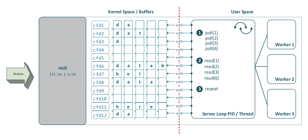
Epoll Syscall
On Linux, epoll() addresses the scalability limitations of poll() and is generally the preferred choice for modern server-side client handling. The following diagram shows how epoll() works in detail:
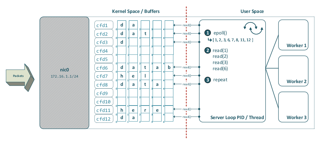
Before epoll(), the classic mechanism was select(), which can also monitor multiple file descriptors—but it does not scale well compared to epoll().
Schematic Non-blocking Server Design
The following diagram shows a logical segmentation into three parts (P1, P2, and P3):
a) P1: the client-handling entity, b) P2: the message-processing entity, and c) P3: the result-sending entity.
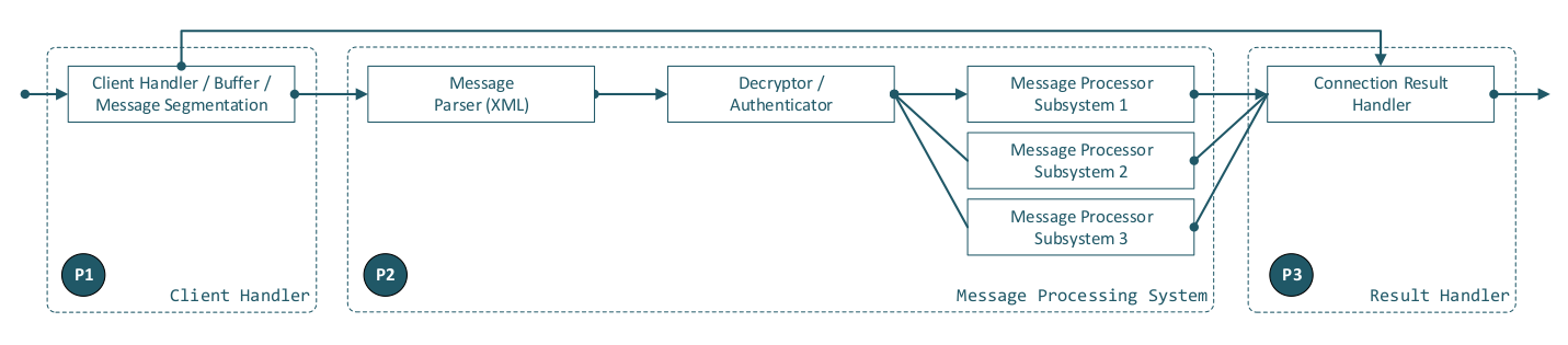
For illustrative purposes, we assume a message-based protocol (HTTP-like, but with modern XML encapsulation). As the diagram indicates, an input payload must pass through the following steps in sequence (left to right):
- Connection data handling / buffering
- Message parsing
- Authentication / payload decryption
- Message payload processing
- Result data sending
Additionally, each entity must be able to communicate with P3 (Result Data Sending) to return error responses at any stage of processing.
Also our specifications define the following behaviour:
- The protocol / server P2 must be capable of processing messages in parallel.
- On a connection, multiple messages may be sent across multiple P1 iterations before P2 message processing has finished.
- On a connection, multiple messages may be sent within a single P1 iteration.
- There must be unique message correlation (e.g., a UUID) between sending and receiving, so the sending client must not wait for a single request to complete.
- A single message part (of fragmented large data) must be sent in strict serial order (this does not conflict with 4.; it applies only to fragmented large data).
Process Separation
Our diagram suggests separating the three parts—P1, P2, and P3—into three operating system processes, potentially with additional worker threads. This decision must be carefully considered: once the design is finalized, changes can become very time-consuming after the main components have already been implemented.
A good protocol design with low overhead (with performance as the priority) is to place P1 and P3 in a single OS process - O1, and P2 in a separate OS process - O2 (or multiple OS processes, depending on what data the protocol must handle). Assume this for the following.
Sleeping
Another highly important OS mechanism is sleeping (e.g., via the nanosleep() system call). Just as humans need sleep to function well, programs sometimes need to wait; otherwise, tight loops may spin at 100% CPU usage, waste power, and potentially create thermal issues.
On Linux, sleep() is a libc wrapper that ultimately uses nanosleep() (or an equivalent kernel sleep primitive). So a sleep(1) (one second) call typically results in a request to sleep for about 1,000,000,000 nanoseconds (1 second).

nanosleep()suspends the execution of the calling thread until either at least the time specified in duration has elapsed, or the delivery of a signal that triggers the invocation of a handler in the calling thread or that terminates the process.
Because our protocol design implies processing (a) new client connections, (b) client data, and (c) result data—and because the process may need to do other work in the future—the main loop should sleep() for a relatively high amount of time when idle (no new connections, no data, and no result-data processing). This is sometimes called the idle_wakeup_time; a reasonable value is often between 10 and 50 milliseconds.
Using a blocking epoll_wait() call in a performance-centric design can be counterproductive. It usually only makes sense if you separate the client handler and the result-data handler into different parallel-running OS processes or threads. However, the process approach requires IPC between those processes (including passing client file descriptors) so the result handler can send data back to clients—adding another layer of complexity and potential performance limitations.
A Programmer’s (Lazy) Imagination
A short remark on human laziness—and on how the networking API is often viewed from an overly simplistic perspective:
We must always keep in mind that the Linux networking API is challenging: due to user-/kernel-space separation and many additional implementation details that may seem counterintuitive at first, its behavior should be questioned and validated through thorough, real-world unit and end2end testing.
Client Socket - Logical Abstraction
In the proposed design, the server loop calls accept() for new client connections and stores the resulting client file descriptor references in an array / vector. The main change to the C++ example in “Server Accept (Blocking)“ is to ensure sockets are operated in non-blocking mode (typically the accepted client socket, not only the listening socket):
int flags = fcntl(server_fd, F_GETFL, 0);
if (fcntl(server_fd, F_SETFL, flags | O_NONBLOCK ) < 0) {
    exit(EXIT_FAILURE);
}

flags = fcntl(client_fd, F_GETFL, 0);
if (fcntl(client_fd, F_SETFL, flags | O_NONBLOCK ) < 0) {
    exit(EXIT_FAILURE);
}
For each server-loop iteration, epoll(), registered with EPOLLIN, tells the server loop which client file descriptors in the vector have data available to read(). The incoming byte stream must be buffered in the client-handler’s data structures. Once one or more complete protocol messages are available in the buffer(s), those messages should be distributed to worker mechanism(s) so that message processing can proceed in parallel.
The following logical “groups” (sub-tasks) are typically required.
Client Socket Data Processing
- No data available right now (rc < 0 && errno == EAGAIN)
- Other I/O error (e.g., network failure) (rc < 0 && errno != EAGAIN)
- Peer closed the connection (rc == 0)
- Data received successfully (rc > 0)
Timeout Handling
- Data receive timeout
- Application data processing / result timeout
Error Handling
- Receive data validation
- Error message formatting / result sending
Application Data Distribution
- Authentication
- Encryption
Result Data Sending
- Send result data / request correlation
Our server design, which combines both receive and send logic within the single O1 process, allows us to build correlations between sender and receiver more easily and to implement timeouts, limits, and error notifications in a very clean way.
The example below demonstrates—in a very simplified form—the Client Socket Data Processing cases an implementer must cope with when calling read() in the server’s client-data receiving section. It is important that, per single server-loop iteration, only one read() per client connection and one write() should be performed.
while (server_exit == false) {
    int rc = read(client_fd, buffer, buffer_size);
    errnr = errno;
    if (rc < 0 && errnr == EAGAIN) { /* continue */ }
    if (rc < 0 && errnr != EAGAIN) { /* set error */ }
    if (rc == 0) { /* msg to log, close conn, remove client conn */ }
    if (rc > 0 ) { append_buffer(); }
    if (timeout) { /* set timeout error */ }
    if (parser.position == end_byte_pos) {
        //- distribute request
    }
    if (distribute_result) { rc = write(client_fd, data, data_length); }
    if (no_new_con && no_client_data && no_send_data) { sleep(idle_wakeup_time); }
}
As you can see, this is straightforward serial processing. There are many cases to integrate, so you may choose a cleaner nested abstraction, but the processing order remains fundamentally serial.
Our proposed design in the O1 process also includes sending result data to the relevant client socket(s) / file descriptors using the write() system call.
In addition to registering epoll() with EPOLLIN, the server should usually also register EPOLLOUT when there is pending outbound data for a socket. This allows the send loop to know, on each iteration, which file descriptors are currently writable, thereby avoiding many unnecessary write() calls per loop cycle under high load.
Finally, many protocol implementations use OpenSSL and encrypt the byte-streamed socket data directly, which adds massive complexity. OpenSSL inefficiently places an SSL* layer “on top of” the client socket file descriptor. More concrete information—and how to avoid this complexity—is provided in the “SSL / TLS” section.
Effective Client Processing
A syscall from user to kernel space triggers a CPU context switch; this is a time-intensive operation compared to direct opcode execution on a single core. Modern CPUs have become more efficient at handling syscalls, but the overhead is still significant, and a server’s architecture relying on too many syscalls can impact performance considerably.
Locking mechanisms are also needed when you pass protocol messages / payloads to threaded or multi-process subsystems that should process data in parallel. Here as well: a kernel mutex (which may involve syscalls) can be used as a memory-locking mechanism, but it is expensive and should be avoided where possible. Atomic, hardware-based CPU operations in combination with shared memory can help speed up server processing substantially.
Especially when designing multi-threaded or multi-process architectures, overly nested or overly complex designs—with an overkill of locking mechanisms—will almost certainly have a negative impact on performance.
Memory
Memory management (memory must be allocated before it can be used) plays a major role in protocol and server architecture.
On Linux, dynamic allocations in user space are typically performed via malloc() / free() (from glibc in many environments). Using these functions correctly will not “harm system stability” by itself. The problem in high-performance servers is cost and scalability: frequent allocations create allocator overhead, increase cache / TLB churn, can amplify lock contention inside the allocator (depending on the allocation pattern), and often lead to fragmentation effects over time.
Consider a server with 5,000 concurrent connections. If each connection allocates a read buffer with malloc() and later releases it with free(), and you do this around every I/O operation, the allocation rate quickly becomes excessive. At 100 reads per connection per second, that is 500,000 allocations and frees per second—pure overhead that does not move any application data forward. A better design is to allocate buffers statically and reuse them.
Also keep in mind that memory performance is shaped by the CPU / MMU and the kernel’s virtual memory subsystem. Access latency can vary significantly due to CPU caches, TLB behavior, NUMA topology (multiple memory controllers / sockets), and page placement. In other words: where and how you allocate memory affects throughput and tail latency.
Static Preallocation
Preallocating buffers can help substantially. In the client-handler process (O1), you can allocate per-connection buffers either:
a) at accept-time (when a new client connects), or b) at server startup (a buffer pool).
Both approaches avoid doing allocations inside the hot path of client-data processing, where repeated malloc() / free() calls are often expensive and unpredictable.
Huge Pages
Modern CPUs/MMUs can address so-called huge pages. Compared to standard pages (4 kilobytes in size), a huge page can be 2 megabytes or 1 gigabyte in size, depending on the CPU, MMU, and operating system used.
So, since nearly all modern CPUs support 2 MB huge pages, why not put multiple buffers into a single 2 MB or 1 GB page for all server connections? Receive buffers for 65,535 connections using 16 kilobytes for each connection nearly fit into a 1 GB huge page and should be more than sufficient.
The drawback of this approach is that you must write your own memory management, but in my opinion it is worth the effort and improves performance significantly.
Some smart guys from the “I want to compress everything” department thought that compression automatically implies better performance and implemented the Linux page compaction feature. In times when 64 GB of memory is a common default, page compaction is often unnecessary and can impact performance significantly—for normal memory and huge pages as well. The Linux kernel sysctl values
vm.compact_unevictable_allowedandvm.compaction_proactivenessshould be deactivated by setting them to0.
Data Distribution / Locking
Data distribution for parallel data processing between threads or processes can also become a bottleneck. A well-designed server architecture—considering all relevant constraints before you start implementation—can mitigate this significantly.
On multi-core systems, shared data structures must be protected against data races. If two threads access the same memory region concurrently and at least one write occurs without proper synchronization, the program has undefined behavior and may crash (sometimes with a segmentation fault).
Locking mechanisms help prevent races, but they must be chosen and implemented carefully. Depending on the mechanism and contention level, synchronization can quickly degrade performance and scalability.
One option is a kernel-backed mutex (e.g., pthread mutexes). Entering the kernel is relatively expensive compared to pure user-space execution, and heavy contention can cause blocking, wakeups, and scheduler overhead.
Atomic operations (lock-free / wait-free primitives) are implemented directly with CPU instructions and are much more lightweight than kernel-backed locking mechanisms because they avoid context switches and scheduler involvement. Even under high parallelism, atomics remain efficient: while they do increase cache-coherency traffic when many cores touch the same cache line, modern CPU interconnects and cache-coherency protocols are designed to handle this. In practice, using atomics enables highly scalable designs—especially when paired with good data-structure layout—and they are often the preferred building block for high-performance concurrent systems.
Following is a short comparison of threading and multiprocessing including some use case scenarios and where they can be used effectively:
Threading
POSIX threads (pthreads) on Linux run within the same process and therefore share the process’s address space: global / static variables, heap memory, code (text) segments and shared-memory mappings. Threads do have their own stacks and are not able to access the process’s stack.
-
If the process’s memory is prepared with well-structured data (typically on the heap or in static / global storage) and threads operate on disjoint (non-overlapping) regions, threading can perform extremely well without any locks, because no shared writable state is contended.
-
If multiple threads execute the same computation (using the process’s code segments) and update a shared variable, that update must be synchronized. Using an atomic operation is very fast and outperforms kernel locking approaches by far.
-
Worker threads using a “queue” in combination with an atomic boolean flag that synchronizes the queue read / write readiness is a common approach and also scales well.
Multiprocessing
In some cases it is advisable to use multiple processes instead of threads, e.g. when security plays a major role and shared code segment execution is a security concern. Data exchange between processes must be handled differently compared to threading.
-
Using Unix domain sockets (
AF_UNIX) withSOCK_STREAMorSOCK_SEQPACKETcommunication,SOCK_SEQPACKEThas been built exclusively for local communication withoutSOCK_STREAMcomplexity. Note that sending / receiving must cross the user / kernel space boundary using syscalls and therefore comes with a certain overhead. -
Using shared memory (
mmap()) directly, multiple processes can access (read / write) shared memory segments directly, but must be synchronized using atomic locks. -
Using shared memory (
mmap()) and external libraries likeboost::interprocess::managed_shared_memory, where C++ objects can be easily mapped into memory and accessed by other processes without memory corruption. Shared access needs additional locking and the memory layout management comes with a given overhead, but enables passing of enhanced data structures which, if self-implemented, need in certain circumstances a lot of code.
Limits
Your protocol should implement explicit limits. Consider the following circumstances:
a) Without strict size limits, a client can send extremely large payloads (e.g., gigabytes) and exhaust server memory, buffers, or disk space—especially if the client implementation is modified (“patched”) or malicious.
b) A server’s processing power is also limited; define maximums that describe this behaviour and inform the client by sending informational messages (this can be very important for proxy processing / scaling).
c) Without rate limits and timeouts, a client can keep connections and server resources busy indefinitely (e.g., slowloris-style behaviour: sending data extremely slowly, holding many connections open, or never completing a request), which can starve legitimate clients.
Real World Examples
The following real-world implementations show two common (and very successful) design directions: highly scalable event-driven I/O with a small number of worker threads, and deliberately minimal single-threaded designs that remove concurrency overhead wherever possible.
- nginx, a widely used HTTP server and reverse proxy, uses
epoll()for scalable I/O and relies on locking (mutexes) where shared state must be protected. - Bjoern, a Python WSGI server, is deliberately single-threaded (“without coroutines or other crap”) and is probably one of the fastest options in its class.
Security Considerations
In practice, the most common and most dangerous attack surface is primarily protocol parsing and the payload-data processing logic at the application layer. Attackers rarely “break TCP” or “break IP”; they exploit mistakes in how an application parses untrusted input, processes payload data, manages memory, and transitions between protocol states.
The lower network layers in the kernel are typically comparatively robust, widely exercised, and heavily audited. That doesn’t mean they’re invulnerable, but most real-world vulnerabilities in network-facing services originate in application code (including custom protocol implementations, ad-hoc framing, and hand-written parsers).
A clean protocol design is therefore a security feature. Well-defined message framing, strict schemas, explicit length limits, and consistent error handling reduce ambiguity—and ambiguity is where exploit primitives often appear. “Be liberal in what you accept” is a reliability strategy, not a security strategy.
Many high-impact vulnerabilities are still caused by classic memory-safety failures: stack / heap buffer overflows and underflows, integer overflows in length calculations, and unsafe copying / concatenation. These bugs become far more likely when parsing is bloated, unstructured, and spread across many special cases.
Binary Versus Text Based Design
One of the most important early decisions in protocol design is the wire format: how messages are represented on the network. The choice between text and binary is a trade-off between debuggability and implementation simplicity on one side, and compactness and strict structure on the other.
A text-based protocol encodes messages as human-readable text (for example JSON, XML, or YAML). A binary protocol encodes messages as byte sequences with a binary layout (fixed fields, variable-length fields, TLV structures, etc.) that typically requires a dedicated encoder/decoder to interpret.
Text-based protocols have two big practical advantages: they are easy to inspect and debug (logs, tcpdump / Wireshark, and simple tooling go a long way), and they are often backed by mature, widely reviewed parsers. When the message format is structured (e.g., JSON or XML), the risk of ad-hoc parsing bugs drops significantly compared to hand-written “split-by-delimiter” logic. If you add a machine-readable schema (e.g., XML DTD/XSD, or a JSON Schema equivalent), you further reduce ambiguity by making the expected structure explicit and enforceable.
Binary protocols are often chosen for compactness and speed, but they come with a common engineering trap: implementers end up writing custom parsing code that is more error-prone—especially around length fields, bounds checks, and state machines. In other words, the performance win can be offset by higher implementation complexity and a larger security risk surface if the parser is not extremely disciplined.
From a performance perspective, text is frequently “fast enough” in real systems—especially once TLS encryption, kernel / user space copies, and general I/O overhead are in the picture. On modern CPUs, the incremental cost of parsing a small-to-medium JSON/XML message is often not the dominant bottleneck. If you do need a binary format, it’s usually best to choose one with a well-defined schema and battle-tested libraries (rather than a bespoke layout), so you get the compactness benefits without reinventing a parser.
Additional practical implications for framing and message boundaries:
-
XML-based protocols don’t inherently rely on fixed byte boundaries / a predeclared message size: in many designs, a receiver can detect message completeness by parsing until a well-formed closing tag (e.g.,
</request>). In other words, the structure itself can serve as a framing mechanism. -
Binary protocols must define framing explicitly: because the payload is not self-delimiting in a human-readable way, the receiver needs a deterministic rule for “how many bytes belong to this message”.
Socket Options
TCP behaviour is highly tunable, and a few socket options have an outsized impact on latency vs. throughput trade-offs—especially for application protocols that perform many small writes. The following options can significantly change how the kernel emits TCP segments (on Linux they can be combined, but in practice you typically use one or the other):
- TCP_NODELAY
- TCP_CORK
TCP_NODELAY disables Nagle’s algorithm. With Nagle disabled, TCP will send small writes as soon as possible instead of buffering them to coalesce data into larger segments. This typically reduces latency for request / response style protocols, but it can increase the number of small packets and thus increase per-packet overhead.
TCP_CORK tells the kernel not to send partial frames: TCP will try to hold back small segments and send them only when enough data has been queued (or when the cork is removed). Linux also enforces a 200 milliseconds ceiling: if data remains corked for too long, the queued data is transmitted automatically. This can improve throughput when you can batch output (e.g., “header + payload”), at the cost of added latency.
SSL / TLS
SSL/TLS (Secure Sockets Layer / Transport Layer Security) is a cryptographic protocol that operates between the TCP transport layer (Layer 4) and the application layer (Layer 7). The current standard is TLS 1.3 (RFC 844616); its predecessor TLS 1.2 (RFC 524617) remains in wide use. SSL itself is deprecated and must not be used.
TLS provides two complementary security services:
-
Transport encryption (confidentiality and integrity): once a TLS handshake is complete, all application data is encrypted before being passed to TCP. An attacker who captures the TCP stream sees only ciphertext. Additionally, TLS uses authenticated encryption (e.g., AES-GCM), which also provides message integrity—any tampering with the ciphertext is detected and the connection is terminated.
-
Authentication and verification: TLS uses X.509 certificates18 (RFC 5280) to authenticate the server (and optionally the client) before the encrypted channel is established. The server presents a certificate signed by a trusted Certificate Authority (CA); the client verifies the certificate chain against its trust store and checks that the hostname matches. This prevents man-in-the-middle attacks where an attacker could otherwise impersonate the server.
OpenSSL Implementation Complexity
The OpenSSL / TLS integration model is often perceived as awkward: TLS is not “part of the socket API,” but a separate protocol layer that sits on top of a transport (usually a TCP socket). In code, that means you no longer call send() / recv() directly; instead, you wrap the socket file descriptor in an SSL* object and use SSL_write() / SSL_read(). Under the hood, OpenSSL still uses the same socket FD for I/O, but it adds its own buffering, record framing, handshake state machine, and error semantics.
This extra layer can complicate application design—especially for implementers building custom, message-oriented protocols. For some protocol designs, applying cryptographic protection at the well-defined message level can be architecturally simpler than integrating a full transport-security layer.
Simplicity Wins
In the previous sections we discussed text-based versus binary protocols. Assume here a message-oriented protocol with well-formed XML framing and schema validation.
For such a design, message-level signing and encryption can be attractive because the cryptographic boundary aligns directly with the protocol message boundary rather than with the raw TCP byte stream. This can simplify application-layer processing in some implementations.
In the concept shown here, this is not based on anonymous key exchange. The communicating peers use X.509 certificates to authenticate the exchanged public keys, but the actual confidentiality and integrity protection is applied at the protocol-message level rather than through TLS record protection.
Take the following protocol message as an example. We also assume that the client and server certificates have already been exchanged—for example, by using X.509 certificates. Once deployed to the client, they provide strong client authentication and support secure transport encryption.
Take the following message example:
<request>
    <UUID>9b327afe-27ae-2367-aef2-e42445e5b23a</UUID>
    <protocol>NLAP</protocol>
    <version>0.1</version>
    <subtype>NLAMP</subtype>
    <header>
        <datetime>2026-03-07-11:36:25:200</datetime>
        <host>host.destination.com</host>
        <user>iamweazle@smartweazle.com</user>
        <UserAgent>WeazleClientv1.0</UserAgent>
    </header>
    <payload>
        #BASE64_ENCRYPTED_PRIVKEY_PAYLOAD_DATA
    </payload>
    <security>
        <signature>
            #BASE64_SIGNED_PRIVKEY_XMLREQ_WITH_UUID_DATE
        </signature>
    </security>
</request>
-
Signing the complete XML request with the sender’s private key can provide strong authenticity and integrity, especially if the signature covers security-relevant fields such as the UUID, timestamp, user identity, and encrypted payload.
-
With this approach, a simple message-oriented cryptographic API is possible, for example:
encrypt_data(algo_type, recipient_pubk_ref, sender_privk_ref, data)anddecrypt_data(algo_type, recipient_privk_ref, sender_pubk_ref, data). -
If the receiver validates timestamp freshness and rejects reused UUIDs / nonces, this design can help mitigate replay attacks.
-
If selected header fields remain intentionally unencrypted, intermediaries such as proxies can use them for routing or protocol dispatch. This improves operational flexibility, but it also exposes metadata and must therefore be considered a deliberate security trade-off.
-
This model can be proxy-friendly for trusted deployments that require protocol-aware routing, provided the exposed metadata is minimal and carefully chosen.
UDP Insights
UDP provides a much simpler transport service than TCP. It is primarily intended for applications that do not require reliable, in-order delivery and that can tolerate loss, duplication, or reordering. UDP also avoids TCP’s connection setup, retransmission machinery, flow control, and congestion-control behavior, which makes it comparatively lightweight and predictable at the transport layer.
What we learned about TCP’s basic characteristics:
- Connection setup via a 3-way handshake
- Flow control and congestion control
- dynamically regulate the sender’s rate based on receiver capacity and network conditions,
- recover from packet loss via retransmissions,
- help protect receivers and the network from overload
- A reliable, ordered byte stream
- No preservation of application message boundaries
- A mature and robust implementation in modern kernels
- Strong isolation through the user space ↔ kernel space boundary
Given these properties, UDP is usually not a good fit for protocols such as FTP, HTTP, or similar download-oriented transports where data must arrive completely and correctly. If packets are dropped, duplicated, or reordered, the application would need to implement acknowledgments, retransmissions, ordering, and some form of rate / congestion handling itself—effectively rebuilding important parts of TCP at Layer 7.
The TCP stack on Linux is highly tunable. Depending on the environment (DSL uplinks, VPNs, satellite links, Linux routers, etc.), TCP parameters can often be adjusted to better match real-world constraints.
So what is UDP good for? UDP becomes attractive when timeliness matters more than completeness.
UDP Real-Time Constraints
Why is UDP useful for real-time workloads? In some scenarios, TCP’s retransmission behavior can become counterproductive. Real-time media such as audio and video often values timeliness over completeness: a packet that arrives too late is no longer useful, even if it eventually arrives correctly.
RTP (Real-time Transport Protocol), which is widely used for audio / video transport including many VoIP systems, is a classic example. If a missing packet causes the receiver to wait too long for retransmission—even tens or hundreds of milliseconds—the media stream may stutter or become audibly / visibly degraded. For real-time playback, it is often better to drop late packets and continue playback than to stall the stream waiting for perfect reliability.
Still, UDP does not magically solve congestion—a full pipe is a full pipe. Real-time systems therefore rely on additional mechanisms and design choices:
-
Playout buffers and loss concealment: RTP receivers typically use a jitter buffer and will drop packets that arrive too late for playback. If packet loss is moderate, codecs and concealment techniques can mask part of the loss; if loss becomes excessive, quality degrades, but the stream can continue.
-
QoS prioritization (where available): Real-time traffic is often marked and prioritized using mechanisms such as DiffServ / DSCP or enterprise QoS. This can reduce jitter and packet loss during short bursts, but it cannot overcome sustained congestion or insufficient bandwidth.
UDP-Lite is even more specialized: it can deliver packets with partially corrupted payloads while still protecting the header. We won’t cover it further here.
Linux Kernel Improvements
A large number of read() and write() system calls can become expensive at high data rates, especially when transferring large files to the network. The cost is not only the system call itself, but also the repeated movement of data between user space and kernel space.
A well-known Linux optimization for this case is sendfile(). In the conventional file-to-socket path, an application typically reads file data from the kernel into a user-space buffer and then writes that buffer back to the kernel so it can be queued for socket transmission. This introduces an unnecessary user-space round trip.
With sendfile(), the application asks the kernel to transfer data directly from a file descriptor to a socket descriptor without copying the file payload through a user-space buffer first. On Linux, this commonly allows the kernel to use the page cache as the source and queue the corresponding pages for socket transmission more efficiently. This is often described as a zero-copy optimization, although the exact data path still depends on kernel internals, socket type, filesystem behaviour, and NIC / driver capabilities. The important practical point is that sendfile() avoids the extra copy into user space and the copy back out again.
sendfile() is particularly effective when the file data is already present in the page cache, because the kernel can then serve the transfer without first reading the data again from storage.
A related optimisation strategy is to map files into user space with mmap(). In that design, file-backed data is accessed through the process address space rather than copied into an explicit read buffer with repeated read() calls. This can reduce copying overhead and may integrate well with application-side parsing or framing logic. Depending on the system design, such mappings may also interact with huge-page mechanisms, although this depends on kernel configuration, mapping type, filesystem support, and whether transparent huge pages or explicit huge pages are actually applicable to that workload.
However, sendfile() is most effective when the payload to be transmitted already exists as file data and can be sent more or less unchanged. Many custom protocols require an application-layer header, footer, framing marker, checksum field, or other metadata around the payload. In such cases, the application usually cannot send the entire protocol message with a single sendfile() call alone: it must prepend and/or append protocol bytes using additional socket operations such as write(), writev(), or sendmsg(). This means that sendfile() can still optimize the transfer of the large payload body, but it does not by itself eliminate all syscalls needed for protocol-aware transmission.
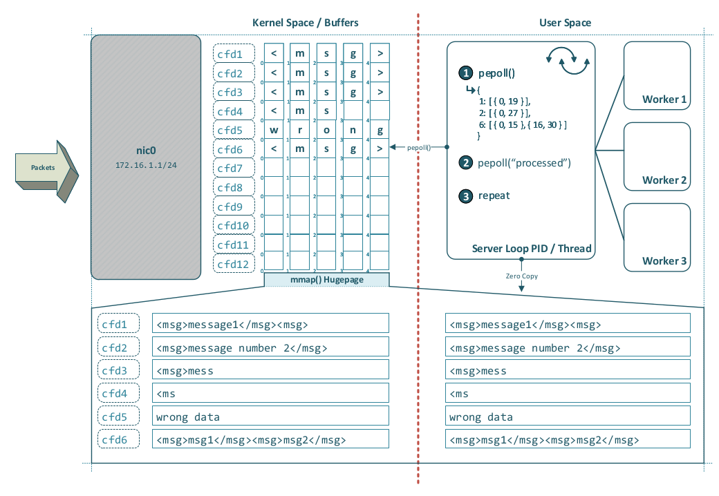
Enhancing epoll() — Message-Aware Readiness
sendfile() demonstrates why reducing user space ↔ kernel space overhead matters, but epoll() addresses a different problem. sendfile() optimizes data movement, whereas epoll() is a readiness notification mechanism for scalable I/O multiplexing, as used by servers such as nginx.
read()partial data and reconstruct complete messages itself?
The idea:
Today, epoll() reports readiness on file descriptors; it does not interpret application-layer framing. For a stream socket such as TCP, that means user space is told only that bytes are available to read or buffer space is available to write—not whether one complete message, several complete messages, or merely a fragment of a message is present.
One could imagine a hypothetical extension—call it Protocol Typed Epoll or pepoll(type)—for protocols with explicit and well-defined framing rules. Such an interface might allow the kernel to:
- buffer incoming bytes until one or more complete frames are available,
- apply basic framing validation,
- discard clearly malformed frames early,
- report completed application messages rather than plain read readiness.
Take the following c-structs as example:
int static_fd_count = 64;
int static_msgs_per_fd = 32;
int fd_count = 10; //- count of filedescriptors having ready messages

struct pepoll_msg {
    uint32_t offset;
    uint32_t length;
};

struct fd_data {
    uint32_t fd;
    struct pepoll_msg messages[static_msgs_per_fd];
};

struct fd_data filedescriptors[static_fd_count];
The following resulting data structure example shows fd5 containing 1 message, fd17 2, fd78 2 and fd89 3 messages:
[
    { 5:  [ { 1, 454 } ] },
    { 17: [ { 1, 258 }, { 259, 1435 } ] },
    { 78: [ { 1, 221 }, { 222, 945 } ] },
    { 89: [ { 1, 523 }, { 259, 1435 }, { 1436, 2189 } ] }
]
Short DNS Protocol Analysis
The following short analysis refers primarily to early/classic DNS as originally specified, without considering later extensions such as EDNS(0) and without focusing on modern encrypted variants such as DoT or DoH. It is useful here because DNS illustrates how a well-designed unencrypted application-layer protocol can combine simple transport usage, retry logic, and practical fallback behavior.
Classic DNS uses UDP port 53 and TCP port 53. These transports are not used in parallel for a single exchange in the normal case. In early DNS, UDP was the default transport for ordinary queries, while TCP was used when a response was too large for the original UDP size limits or when the operation itself required a reliable stream, such as a zone transfer.
For large DNS responses or zone transfers between authoritative servers, TCP is therefore commonly used. The reason is not simply that TCP is “better,” but that it provides reliable, ordered delivery with retransmission and flow control, which is particularly useful when data must arrive completely and correctly.
If a UDP-based DNS exchange fails because a packet is lost in transit or no response arrives within the configured timeout, the retry logic is handled at the application layer (Layer 7) by the DNS resolver implementation. TCP-based exchanges may also fail and be retried by the application, although this is generally less common because TCP already provides transport-level recovery mechanisms.
A practical strength of DNS is that resolvers can query multiple configured DNS servers, usually trying them in a defined order rather than all at once. This provides a form of redundancy by design. The drawback of this serial strategy is increased lookup latency if one server is slow or unreachable and the timeout is configured too generously.
For high-scalability DNS systems, anycast is widely used to distribute queries across multiple geographically or topologically distributed servers that share the same IP address.
DNS is a good example of how an application-layer protocol can remain relatively simple while still implementing practical retry and failover behavior above the transport layer. That does not mean every protocol should copy DNS directly, but it does show that protocol designers should think carefully about which reliability and fallback mechanisms belong in the application protocol and which should be left to the transport layer.
Closing Words
Thank you for reading “Beyond the Socket API.” Network programming is a complex discipline, but many of its practical challenges become easier to reason about once the boundaries between application logic, kernel behavior, and the physical network are clearly understood.
In real-world deployments, it is important to keep perspective: many modern Internet and enterprise networks—especially fiber connections, VDSL links, and well-operated LAN environments—are stable enough that severe congestion is comparatively uncommon. In such environments, the transport layer is often not the primary source of latency. More often, performance problems originate at Layer 7: inefficient protocol framing, poor buffering strategies, weak backpressure handling, unnecessary threading complexity, or suboptimal I/O design.
This is one reason developers should be careful not to draw the wrong conclusion from isolated packet loss or short recovery events. If an application can tolerate a healing or recovery window in the range of roughly 200 milliseconds to 2 seconds, abandoning a mature and reliable transport such as TCP in favour of UDP is often the wrong engineering decision. TCP already provides retransmission, ordering, flow control, and congestion control in a robust and well-tested form. Replacing those guarantees at the application layer usually increases complexity, weakens correctness, and shifts responsibility to code that is often far less battle-tested than the kernel’s TCP/IP stack.
That said, network conditions are never universally ideal. Customer Wi‑Fi in particular remains a frequent source of jitter, packet loss, and timing irregularities due to interference, DFS events, contention, and other radio-layer effects. In those environments, no transport protocol can guarantee perfect behavior under all circumstances. The right response is therefore not protocol dogmatism, but careful engineering: choose the transport whose guarantees match the application’s true requirements, and design the application layer so that it behaves predictably under imperfect conditions.
For many systems, that still means TCP is the correct default choice. Reliability, ordering, and recoverability remain powerful advantages, and in increasingly well-performing network environments they are often worth far more than the perceived benefit of avoiding occasional retransmission delays.

Network programming is a complex subject that benefits from careful study, rigorous implementation, and thorough testing. If you found the diagrams, code examples, or conceptual explanations helpful, consider sharing this article with colleagues working on network-facing applications.
Questions, corrections, and discussion are always welcome. The author can be reached via the contact information on der-it-pruefer.de.
References and Further Reading
Advanced Topics
- Internet Control / Group Message Protocol (ICMP, IGMP)
- Jumbo Frames and MTU - Ethernet frame sizing and fragmentation, ICMP Path MTU Discovery
- IP addressing modes (broadcast / multicast / anycast)
- Link aggregation (IEEE 802.3ad) - channel bonding multiple interfaces
- Hardware offloading (Checksum Offload, Segmentation Offload) - NIC features that influence performance and packet visibility
- Spanning Tree Protocol (STP / RSTP / MSTP) - loop prevention in Layer‑2 switched networks
- Quality of Service (DSCP / ToS / DiffServ / RSVP) - classification, marking, and prioritization
- Traffic shaping and policing (tc / Linux Traffic Control) - rate limiting, queuing disciplines, bufferbloat mitigation
- VPN tunneling and encapsulation (L2TP / IPsec)
- Network security mechanisms and attack vectors (ARP spoofing / poisoning, DHCP snooping, Dynamic ARP Inspection)
- Network segmentation and isolation (VLAN segmentation, ACLs)
Related Articles
- Prüfer, C. (2025). OS Kernel Network Abstraction – Ring 0 Protection. Der IT-Prüfer. https://www.der-it-pruefer.de/os/OS-Kernel-Network-Abstraction-Ring0-Protection
Related Projects
- Prüfer, C. (2026). NLAP – Next Level Application Protocol. GitHub. https://github.com/WEBcodeX1/http-1.2
External Resources
- TCP Three-Way Handshake – NetworkWalks
- Writing Custom Linux System Calls: A Complete Guide
- Linux File Descriptors – Wikipedia
- Linux man pages – socket(2)
- Linux man pages – bind(2)
- Linux man pages – listen(2)
- Linux man pages – accept(2)
- Linux man pages – epoll(7)
- OpenSSL Documentation
-
The BSD socket API was introduced in 4.2BSD (1983): WIKIPEDIA – Berkeley sockets ↩
-
RFC 826 – An Ethernet Address Resolution Protocol (ARP): https://www.rfc-editor.org/rfc/rfc826 ↩ ↩2
-
RFC 793 – Transmission Control Protocol (TCP): https://www.rfc-editor.org/rfc/rfc793 ↩ ↩2
-
RFC 9293 – Transmission Control Protocol (TCP) – updated specification: https://www.rfc-editor.org/rfc/rfc9293 ↩ ↩2
-
RFC 768 – User Datagram Protocol: https://www.rfc-editor.org/rfc/rfc768 ↩ ↩2
-
RFC 3828 – The Lightweight User Datagram Protocol (UDP-Lite): https://www.rfc-editor.org/rfc/rfc3828 ↩ ↩2
-
ISO/IEC 7498-1 – Open Systems Interconnection – Basic Reference Model: WIKIPEDIA – OSI model ↩ ↩2
-
IEEE 802.3 - Ethernet WIKIPEDIA – IEEE 802.3 ↩
-
IEEE 802.1Q - Virtual Local Area Networking WIKIPEDIA – IEEE 802.1Q ↩ ↩2 ↩3
-
IEEE 802.3x – Ethernet flow control (PAUSE frames): WIKIPEDIA – Ethernet flow control ↩ ↩2
-
RFC 791 – Internet Protocol, Version 4 (IPv4) Specification: https://www.rfc-editor.org/rfc/rfc791 ↩ ↩2
-
RFC 8200 – Internet Protocol, Version 6 (IPv6) Specification: https://www.rfc-editor.org/rfc/rfc8200 ↩
-
RFC 896 – Congestion Control in IP/TCP Internetworks: https://www.rfc-editor.org/rfc/rfc896 ↩
-
IEEE 802.3ad – Ethernet link aggregation: WIKIPEDIA – Link aggregation ↩
-
RFC 6298 – Computing TCP’s Retransmission Timer: https://www.rfc-editor.org/rfc/rfc6298 ↩
-
RFC 8446 – The Transport Layer Security (TLS) Protocol Version 1.3: https://www.rfc-editor.org/rfc/rfc8446 ↩
-
RFC 5246 – The Transport Layer Security (TLS) Protocol Version 1.2: https://www.rfc-editor.org/rfc/rfc5246 ↩
-
X.509 - Public Key Certificates WIKIPEDIA – X.509 ↩