Search Results:
Allied telesis switch config part1
posted on 08 Feb 2025 under category network
Allied Telesis - Virtual Chassis Stacking / LACP / Linux / VLAN Setup
Post Meta-Data
| Date | Language | Author | Description |
|---|---|---|---|
| 08.02.2025 | English | Claus Prüfer (Chief Prüfer) | Allied Telesis - Virtual Chassis Stacking LACP |
Foreword
Over the past decades, I have worked with a variety of switch vendors. The pace of switch development remains remarkably rapid as Internet core switching and cloud services demand ever-increasing speeds.

As of 2025, the industry is advancing toward the IEEE 802.3 800 / 1600 GbE standards, with even greater speeds under research and development.
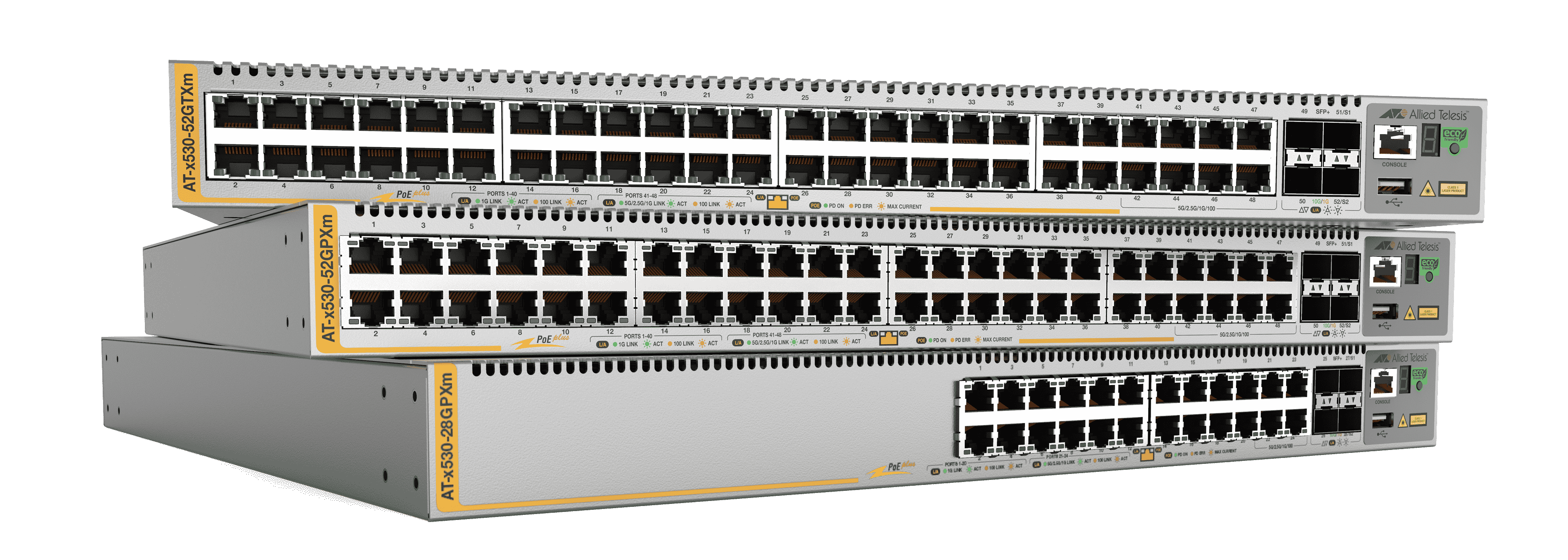
Before delving into configuration details, a brief overview of Allied Telesis switches is warranted.
The Selection Process
A recent client project prompted me to search for a suitable switch vendor. The following prioritized requirements guided my decision:
- Stability under maximum load
- Multiple redundant power supplies
- Reliability and support for switch stacking
- Comprehensive security (SNMPv3)
- 10GbE Ethernet capability
- LACP support
- IEEE 802.1Q VLAN
- IP routing / Layer-3 functionality
- Fast IPv4 and IPv6 firewalling
- Software Defined Networking (SDN)
- Minimum 9k jumbo frame size for both switching and routing
- Multiple Spanning Tree Protocol (MSTP)
- 802.3x flow control
- Intuitive and logical CLI
- Favorable price-performance ratio and licensing
Allied Telesis emerged as a promising candidate.
After comparing and testing several models from different vendors, I concluded that Allied Telesis switches will be my preferred choice for future enterprise projects.

Multi-Interface Bonding
This section demonstrates LACP (Link Aggregation Control Protocol) bonding, with port group members distributed across multiple, stacked (VCStack-enabled) switches.
Such a setup is essential for 24/7 datacenter operations requiring 99.9% reliability.
Prerequisites: To fully understand the example and configuration, the following knowledge is recommended:
- Fundamental networking and TCP/IP concepts
- Familiarity with Allied Telesis switch CLI syntax
- Advanced networking (LACP and VLAN configuration)
- Linux networking, specifically netplan.io
LACP Across Two Stacked Allied Telesis Switches
The switch model AT-x530L-28GTX is used in this example.
Additionally, VLAN trunking configuration atop the bond will be discussed.
Physical Cabling Overview
Stack cabling utilizes fiber ports.
- port1.0.27 connects to port2.0.27
- port1.0.28 connects to port2.0.28
Switch #1
bd1 (eth0 interface on server side)
 | +--------+---------------------------------------------------------+---------+
 +-| P1.0.1 |                                                         | P1.0.27 |----+
   +--------+---------------------------------------------------------+---------+    |
   | P1.0.2 |                                                         | P1.0.28 |--+ |
   +--------+---------------------------------------------------------+---------+  | |
                                                                                   | |
Switch #2
                                                                                   | |
bd2 (eth1 interface on server side)                                                | |
 | +--------+---------------------------------------------------------+---------+  | |
 +-| P2.0.1 |                                                         | P2.0.27 |--|-+
   +--------+---------------------------------------------------------+---------+  |
   | P2.0.2 |                                                         | P2.0.28 |--+
   +--------+---------------------------------------------------------+---------+
Enabling VCStack
Enable VCStack mode on both switches via serial console:
awplus> enable
awplus# configure terminal
awplus(config)# stack enable
Assign priority “0” to the primary (master) switch:
awplus(config)# stack 1 priority 0
Enable stackports on both switches:
awplus(config)# interface port1.0.27
awplus(config-if)# stackport
awplus(config)# interface port1.0.28
awplus(config-if)# stackport
After stacking is configured, port numbering on switch #2 changes to “port2.*”.
Verifying VCStack Operation
You can confirm stacked mode by:
- Observing switch LEDs (for stack member ID)
- Reviewing configuration output
Use the following command to inspect system and stack status:
awplus> enable
awplus# show system
Switch #1 (Stack member 1):
Stack member 1

Board      ID   Bay     Board Name             Rev   Serial number
---------------------------------------------------------------------
Base       567  Base    AT-x530L-28GTX         A-1   Axxxxxxxxxxxxxxx
---------------------------------------------------------------------
RAM: Total: 1028784 kB Free: 822200 kB
Flash: 208.2MB Used: 31.5MB Available: 176.8MB
---------------------------------------------------------------------
Environment Status : Normal
Uptime             : 0 days 00:52:29
Bootloader version : 7.0.15
Switch #2 (Stack member 2):
Stack member 2

Board      ID   Bay     Board Name             Rev   Serial number
---------------------------------------------------------------------
Base       567  Base    AT-x530L-28GTX         A-1   Axxxxxxxxxxxxxxx
---------------------------------------------------------------------
RAM: Total: 1028784 kB Free: 826252 kB
Flash: 208.2MB Used: 31.5MB Available: 176.8MB
---------------------------------------------------------------------
Environment Status : Normal
Uptime             : 0 days 00:52:26
Bootloader version : 7.0.15
Server Configuration
Base System Properties:
+-------------------------+----------------------------------------------+
| Property                | Value                                        |
+-------------------------+----------------------------------------------+
| Operating System        | Ubuntu Linux 22.04.3 LTS - Server            |
| Network Ethernet Card   | 2-Port Intel 10GbE (ixgbe)                   |
| Network Configuration   | netplan.io                                   |
+-------------------------+----------------------------------------------+
Detailed configuration is provided in “Configure Bond Master (Server)” below.
Cabling Summary
- port1.0.1 connects to server’s eth0
- port2.0.1 connects to server’s eth1
All switch ports overview, including bonding ports:
+----------+------------+---------------------------------------------+------------+
| Switch # | Port Src   | Description                                 | Port Dst   |
+----------+------------+---------------------------------------------+------------+
| 1        | P1.0.1     | Uplink to Linux eth0                        | Linux eth0 |
| 1        | P1.0.27    | Fibre Uplink 1                              | P2.0.27    |
| 1        | P1.0.28    | Fibre Uplink 2                              | P2.0.28    |
| 2        | P2.0.1     | Uplink to Linux eth1                        | Linux eth1 |
| 2        | P2.0.27    | Fibre Uplink 3                              | P1.0.27    |
| 2        | P2.0.28    | Fibre Uplink 4                              | P1.0.28    |
+----------+------------+---------------------------------------------+------------+
Switch Configuration Steps
Enter configuration mode and authenticate:
awplus> enable
awplus# configure terminal
awplus(config)#
Channel Group Properties
Set LACP mode to passive on the switch side. The server will use active mode.
The LACP system-priority on the switch should be higher than on the server.
awplus(config)# lacp global-passive-mode enable
awplus(config)# lacp system-priority 20000
Configure Bonding Ports
Configure bonding on ports port1.0.1 and port2.0.1:
Once stacking is enabled, the two switches function as a single virtual switch. CLI commands can be entered on either switch (via serial or TCP/IP); configuration applies to both.
awplus(config)# interface port1.0.1
awplus(config-if)# channel-group 1 mode passive
awplus(config)# interface port2.0.1
awplus(config-if)# channel-group 1 mode passive
This creates the po1 LACP bonding interface, to which VLANs can be assigned.
Configure VLANs
Create two VLAN trunks atop the bond:
awplus(config)# vlan database
awplus(config-vlan)# vlan 10 name net1
awplus(config-vlan)# vlan 20 name net2
awplus(config)# vlan 10,20 state enable

awplus(config)# interface po1
awplus(config-if)# switchport mode trunk ingress-filter disable
awplus(config-if)# switchport trunk allowed vlan add 10,20
Corresponding VLAN trunk setup must be added to the server’s bond interface.
Configure Bond Master (Server)
Adapt interface names to match your server’s hardware.
- /etc/netplan/01-network-renderer.yaml
network:
    version: 2
    renderer: networkd
- /etc/netplan/02-bond-config.yaml
network:
    version: 2
    bonds:
        bond0:
            interfaces:
                - enp193s0f0
                - enp193s0f1
            parameters:
                lacp-rate: fast
                mode: 802.3ad
                transmit-hash-policy: layer3+4
    ethernets:
        enp193s0f0: {}
        enp193s0f1: {}
- /etc/netplan/03-vlan-config.yaml
network:
    version: 2
    renderer: networkd
    vlans:
        bond0.10:
            id: 10
            link: bond0
            dhcp4: false
            dhcp6: false
            addresses: [192.168.1.10/24]
        bond0.20:
            id: 20
            link: bond0
            dhcp4: false
            dhcp6: false
            addresses: [192.168.2.10/24]
Verifying VLAN Setup
To test the configuration, configure two independent access ports on the switch (first for VLAN 10, second for VLAN 20).
Connect clients to each port, assign static IP addresses, and attempt to ping the corresponding server IP addresses.
awplus(config)# interface port2.0.23
awplus(config-if)# switchport mode access
awplus(config-if)# switchport access vlan 10

awplus(config)# interface port2.0.24
awplus(config-if)# switchport mode access
awplus(config-if)# switchport access vlan 20
 Mission accomplished. Enjoy a well-deserved coffee break.
References and Further Reading
- Allied Telesis Product Information
- LACP / IEEE 802.3ad Standard
- Ubuntu Netplan Documentation
- VCStack Technology Overview
End of Part 1